VK3HJQ
![]()

WIFI Page
Eric's Mod
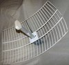
Eric's famous modification that is a simple and effective mod for converting a 2.195GHz MDS Microwave TV Antenna to 2.4GHz WiFi.
Introduction
Dr. Eric Lawrey of Codevalley Pty Ltd, using the resources of James Cook University and assisted by Noel Lovisa and Simon Willis, has designed a modification of the 2.195Ghz antennae that were used for for the now defunct Austar's MDS service, long since replaced by a satellite service. The modification makes the antennae suitable for use in the 2.4GHz band utilized by 802.11b/g technologies. The antennae, which still dot many roofs around Townsville make an ideal resource for the Townsville community wireless mesh.
The modification was called for after a search for Austar modifications turned up several basically similar mods that were rather crude. These mods relied on attaching 50 Ohm coax directly to the driven element with the result that rarely could a connection be made that provided any suitable matching. This was reflected in the forums where those who were lucky got good results while others, with what appeared to be an identical mod, had poor or no results.
Eric's Mod solves these consistency problems by using some of the dipole's existing matching circuitry. Soldering and trimming are still required, but are simpler and deliver very repeatable results. Anyone who can borrow a soldering iron and a craft knife should be able to perform this modification. Coupled with the original 19dB grid antenna that comes with the Austar dipole, you have a cheap, powerful 802.11b/g antenna.
Thank you to the following people and organisations for their aid in this project:
NB: More detailed instructions and photographs are coming as soon as we build a few more.
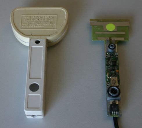
Step 1 : Open the Austar dipole case in the usual way. They are usually sealed, so you may need to use a hacksaw to cut away part of the plastic. Try not to totally detatch the two sections of case, as the dipole can be slid out from between them and it will be easier to weatherproof later.
Opening the case
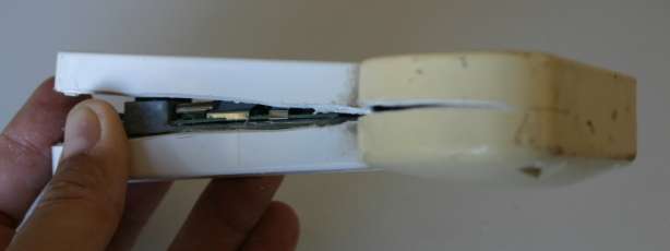
Case open
Step 2 : Remove the clip-on shields from top and bottom of the circuit board. Save these clips for later use.
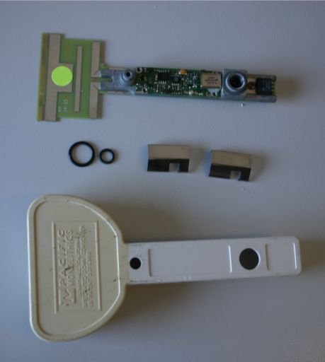
Circuit board removed ( and shields )
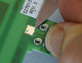
Step 3 : On the bottom circuit board (the one with the elements) remove the receive pre-amp. It is a tiny circular black device with 4 pins. Usually it has a single letter "A" printed on it. One of the pins leads up to a square pad (approximately 5mm x 5mm) which has a via to the driven element on the other side. Remove the preamp carefully because you will need to connect a coax center core to its input pad. Using a soldering iron, put a blob of solder over the whole device and tap the circuit board on the table and the device and solder will fall off revealing a small tinned pad of the track that goes up to the driven element. An iron that is too hot will lift the tracks. If the track does lift, trim the lifted portion and scrape back some of the green solder mask to reveal the copper thus forming a new pad. We even have a working antenna with a connection directly to the square pad but we have not measured its relative performance.
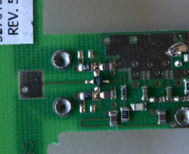
Pre-amp
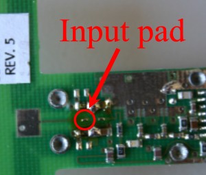
Connection point
Step 4 : Score and trim 0.5mm off the left and right side of the square pad that the pre-amp track is attached to. The copper should peel easily. This modifies the matching to the driven element on the other side of the board by reducing the capacitance.
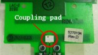
Location of the coupling pad
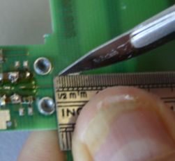
Trimming coupling pad
Trimming coupling pad
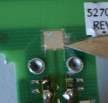
Finished mod
Step 5 : Score and trim each member of the driven element to 17mm (from its 23.5mm. Do not touch the director element or the reflector element. These can be identified easily because they are not attached to anything.
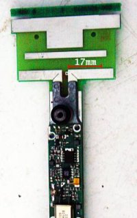
17mm measurement
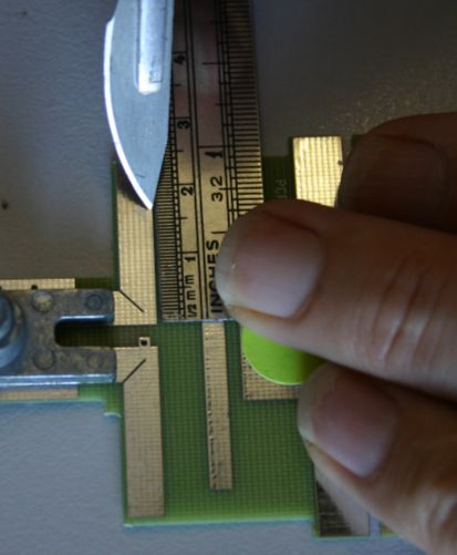
Marking element
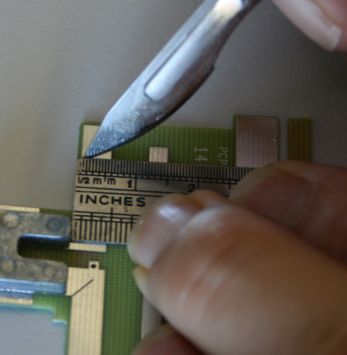
Trimming the driven element
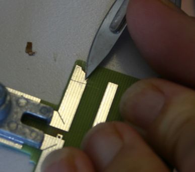
Removing trimmed element portion
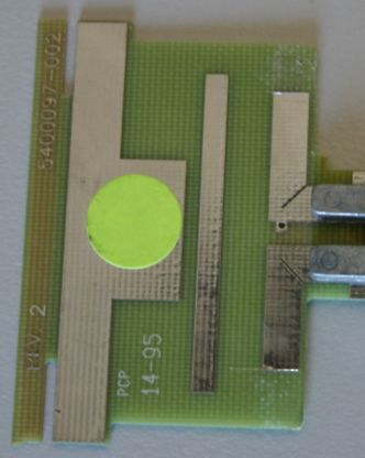
Finished mod
Step 6 : Attach some cheap, lossy RG58 coax to the tinned pad that was formerly attached to the pre-amp. Divide the shield of the coax into two and solder to anything either side of the pre-amp pad (most are ground, and this also helps to anchor the coax). Make sure you solder the shield first, as people have attached the core to that tiny pad only to have the cable twist during handling resulting in the pad being ripped up. With the shield securely attached, attach the core. Don't bother with a continuity test as the matching circuit at DC is connected to ground so your coax will look like it's short circuited.
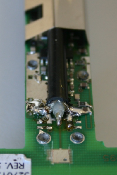
Coax attached
Step 7 : Using the shield clips saved earlier, anchor the coax to the circuit board. These are better than zip ties because the cross section of the board is maintained - and they're free.
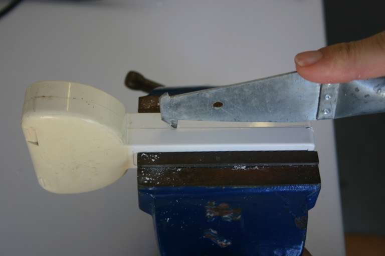
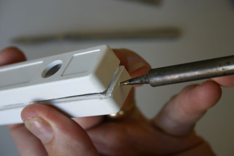
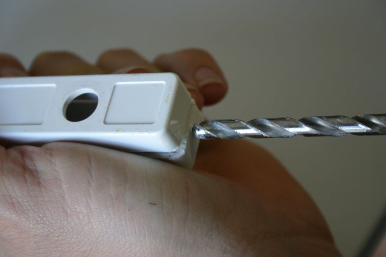
Step 8 : Drill a hole in the base of the dipole case for the coax to exit. A simple trick to ensure perfect centering is to use a soldering iron to make a small indentation in the plastic. This indentation can be used to position the drill bit. Please use a bench vice for this step :-)
Coax attached
Coax attached
Step 9 : Reassemble the dipole in the case. It will all fit and the screw and connector can be used to give the circuit board its natural anchor points and positioning.
Coax attached
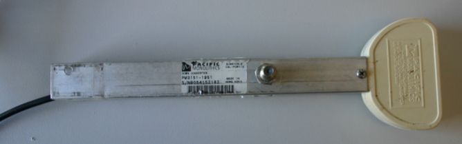
Assembled
Step 10 : Enjoy a cheap, quality antenna with gain as good as the original. You will probably need to weatherproof the dipole case; a tough plastic bag and duct tape should be sufficient.

Finished product
This mod is in use for several hops greater than 10km
around the Townsville region, with multi-megabit results.
Experimental data coming soon. Eric and Noel have performed tests using JCU equipment, and details will be placed here after thorough analysis, or it seems when we get around to it.
VK3HJQ Home Page

© vk3hjq 2001-2022 All Rights Reserved. vk3hjq@hotmail.com