VK3HJQ
![]()

RT85 Page
Thanks to Brad Wooding VK3TAE
This page has been put together to try
solve the programming mysteries behind the RT85 series radios.
Many hours have been spent on the following information so I hope it is
useful to all the amateur radio operators.
Regards Brad VK3TAE
There are 4 versions of the RT85 that I know of.
RT85
Has a 2716 Eprom. Standard version.
The Eprom is soldered to an interface board and is programmed via a stand alone programmer. A converted Midland 70-1000 with RT85 S/W in it or the PC version 70-1000C. The PC version will not do 12.5Khz on VHF option 15F.
RX and TX SYNTHESISER ALIGNMENT is the same for all models. Place a meter on TP701 and adjust L102 to 3.5V Ctr Freq. Min V = 1.7 Max V = 6.0 If the vco is not locked the speaker will sound a tone and the up / down will not function on the control head. The VCO has an out of band of around 10Mhz.
TX VCO Place a meter on TP702, disconnect the exciter output. Press PTT and adjust L102 to 3.5Vdc Min V = 1.7 Max V = 6.5
Test for the Highest freq and the Lowest freq that it stays balanced between the Spec's.
PA alignment
All on models the PA is touchy. The PA driver can be put onto overdrive
and go up in smoke. You have to get the max power with the
minimum current. If you drive the PA to max power the current
drawn will be excessive and damage will occur.
Connect a 50ohm load, Adj CV102 for max pwr out. Set RV502 on PA
fully clockwise,operate PTT and adjust CV501, then
CV502, CV 503 and finally CV504 to Max power out. Note: The RT85C
has no low power feature.
If out of band and alteration to the cap in
the PA is not done, back C504 off to Min Current with max power to
avoid damage to PA.
A typical radio power is 18 - 20 Watts around 5 amps, at 25 w = no more
than 7.5amps. Even though the radio is a 25W Radio and the Main
PA transistor is 30W the caps around the PA will get hot out of band
with the excess current break down and damage will happen.
Low Power The low power is adjusted on the PA board RV502 is for high, RV501 is for low. The power level is switched by the operator by shorting out P302 and P303 in the control head. Adj RV501 for desired o/p
RX Alignment. Apply a RF signal Generator to the antennae socket and provide sufficient RF input level.
Adjust the following in order CV202 and CV203 of max sinad.
Adjust L201, L202, L204, L205 vhf lo band
Adjust L201, L202, L204, L205 and L206 for vhf hi band
Adjust L201, L202, L203, L204, L205 and L206 for uhf band
Frequency Netting is adjusted with CV701
Audio Level Set
vol fully clockwise, set sig gen to 1Khz +3Khz dev, Adj RV252 for 3.7 -
4v RMS on speaker Squelch threshold sensitivity adj RV251
Mic audio is adjusted RV101 for 5khz max then RV102 for 3khz dev.
Speaker connections. The speaker plug in to +P304 and -P305 on the control head. Stripe is usually positive
Going out of band.
The VCO will stretch about 20Mhz up and about 10mhz down but the PA
power will be down a bit. Just don't drive it flat out. The
RX side should be around .25uV for 12dbsinad.
MODEL NUMBERS
1LM 82271 70 - 85Mhz
1LM 82272 148 - 174Mhz
1LM 82273 400 - 420Mhz
1LM 82274 450 - 475Mhz
1LM 82275 470 - 500Mhz
1LM 82276 495 - 520Mhz

rt85.pdf This is the personality code for the rt85
RT85A
There is two versions.
Version One
has a 2716 Eprom. The Microprocessor has RT85A stamped on it but
like the Motorola Syntrx it is a M6805 microprocessor with a different
label
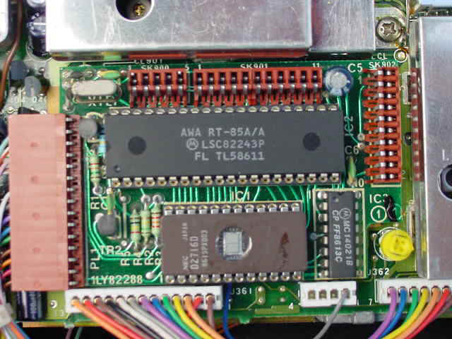 2716 Version 1
 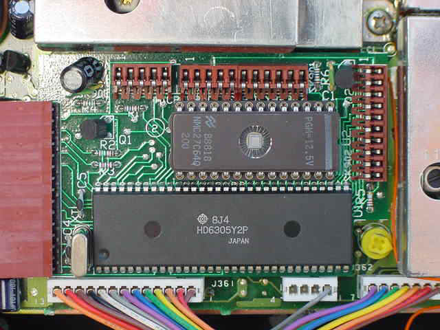 2764 Version 2
Version Two has a 27C64 Eprom. The Microprocessor is a Hitachi HD6305Y2P.
The RT85A can have 100 ch's. Ch 00 to 99.

RT85A Controller side with the 2716 RT85A RF side with Selcall
and CTCSS
Board fitted
The RT85A-1 Ver 1.7 Basic S/W is based on
the 2764 version. It is not recommended to program the 27C64
version of radio with ver 1.7 as the personality is incorrect in the
program.
The RT85A.bas will not program the options correctly. The freq data can
be used to make the programming easy but the options area differ to the
radios. The RT85A.MOB file is the master file loaded at Loc 0000,
the freq.bin file is loaded over the top at location 1000 Hex. You then
must manual edit location 13F0 to get the radio to function correctly
The microprocessor is a HD6305Y2P Hitachi IC. The basic file will not program to this micro so manual editing has to be preformed if anything other than the frequencies is required.
The scan channels are at the same locations as in the standard RT85. The rt85a.bas file in the RT85A-1 ver 1.7 of the S/W write these incorrectly.
eg: You can prog the scan at the locations 1000, 1004, 1008, 100C etc and enter the channel number in any order. Set location 13F3 to 41. The problem to solve is after ch40 the set locks up when scan is pressed. Then the micro has to be reset.
The RT85A-1 program as another error in it in the save function.
When you load a saved *.ABV file it will
load all the abbreviations into the program. You then press enter
and it will load in all of the channels. Then press
"X". This will put you in to the last menu to edit or save files.
When you edit "A" field you can press 1,2,3 or 4 to alter option.
When you select scan and exit the edit you must save the file to the
ABV format before entering the scan channels. If not the ABV file
will be useless to recall. The ABV file will not contain the
options or channel data. It is a good option to save to a
different file name to preserve the master ABV file. This will
save you hours of typing the channels in again.
If the Eprom errors while testing the unit the up/down will lock up. If you turn the radio off and back on again the radio busy light will say on and channel still be locked out.
RESETTING THE MICRO HD6305 on the 27C64 Version
Simply remove the power and pull out the eprom board.
Short out C3 the electrolytic cap on the board.
The eprom can stay in if you wish to keep on testing it.
Place back in the power up.
PROBLEMS FOUND WITH THE RT85A's
The main problem that the manufacture made the
eprom board pins to short so, if you don't pack the eprom board down by
placing packing between the lid and eprom board the radio will play up.
EPROM FILES TO DOWNLOAD FOR THE RT85A-2716 Version
rt85a-16.mob This is the standard source code of the RT85A-2716,RDNS version
A16-70cm.bin This is a file for the RT85A-2716 version on 70'cm's. Scan 1 to 30.
master-a.bin
This is a different version of the operating code for the 2716 version
extracted from another RT85A radio I did years ago
EPROM FILES TO DOWNLOAD FOR THE RT85A-2764 Version
64a-70cm.bin This is for 70cm's 430-440Mhz. Scans Vic Repeaters,Low power now fixed and time out timer longer.
70cm-vs.pdf This is the frequency list of rt85a-70cm.bin file (same freq's for C version)
RT85C
The RT85C is Known as an EXICOM
RT85C. It is Basically a Midland 70-530A. It uses the same
boards as the RT85 series but has a different controller board. The
Microprocessor is a Hitachi HD6305Y2P.
The RT85A can have 100 ch's. Ch 00 to 99.


RT85C Label
Front view of the unit. Notice the case is
not cast al but steel
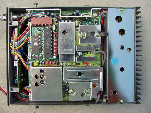
The eprom is a 27C64 and is located on the Controller Board. This board
is located on the RF side of the Radio and is turned face down. To
remove the eprom you have to remove the board out of the radio.


The RF side with the controller Board. The HD44840A27 on the VCO board.


The controller has Selcall and CTCSS on. The RT85C PA swivels down to align
The PA is accessed by folding down and turning 90 deg. Unlike the other RT85's which is inline.
Unlike the RT85A software the RT85C PC based software works well.
EPROM FILES TO DOWNLOAD FOR THE RT85C
70cm-vic-scan.bin This file is for 70cm's Scans all Victorian Rpts
70cm-vic-scan.pdf This is the frequency list of 70cm-vic-scan.bin file
rt85c.pdf Programming personality information
RT85 Control head

Modifications to standard head, to convert to/from the RDNS control head
The standard head has ground as input to the Send/Status switch and outputs to the bar "send" line to the radio body.(via pin 26)
The RDNS control head has button common as input to the Send/Status switch and outputs to IC313
|
Standard |
RDNS |
|
|
W1 |
In |
Out |
|
W2 |
Out |
In |
|
W3 |
In |
Out |
|
W4 |
Out |
In |
W1 selects ground as input to Status/Send button
W2 selects button common as input to Status/Send button
W3 selects "send" as output of Status/Send button
W4 selects IC313 as output of Status/Send button
RNDS UNITS.
There has been many radios hit the Amateur market in the last few months that came from the Royal District Nursing Service. They had a Selcall set up and an Emergency call function. The Micro code is different to a normal RT85A or C versions.
The Micro code has a second function in it to activate the Selcall remotely. This was done by the Nurse carrying a small pager type transmitter. This unit has the 6 RNDS freq's in it. When an Emergency arrived at the location the nurse was visiting the button was pressed it would TX a Selcall to the car radio and then put the car radio in a emergency state. The car radio would then automatically TX the Selcall to the Base so help could arrive.
To get around this function and disable the emergency function, the Red button on the remote head has been disconnected and the selcall in the radio personality has been disabled.
If you have any more information that you think is useful it would be appreciated and I will add it on.
MORE INFORMATION
Mark VK3BYY has done some R and D on the RT85A unit as well and here is the page to view www.qsl.net/vk3byy/rt85data.html
VK3TAE takes no responsibility for the above information. It is to be used as a reference guide only.
Last update 27-03-2002
VK3HJQ Home Page

© vk3hjq 2001-2022 All Rights Reserved. vk3hjq@hotmail.com